
As an IoT (Internet of Things) shop, we love working with new technology and creating fun useful side projects. We have worked on everything from a temperature sensor for the office, to a boost controller for a Subaru WRX. So when one of our staff was working on a theater room for his house, we were more than ready to lend a hand with a fun IoT project!
There is a half stair that leads into the theater room that presented such an opportunity. In traditional theaters, there are usually small lights attached under the stairs to give people enough light to walk down the aisle, but not too much to distract from the movie. It would be so cool if this theater room had such a light that was also interactive!
In order to accomplish this, we needed to attach a multicolored LED light strand underneath the stair. It would need to be a compact, unobtrusive, and easily controllable. The options were endless! We wanted to be able to customize patterns, colors, and change the lights to fit the mood of the room (or the movie!). With the size requirements for the project, in came the Raspberry Pi Zero.
How to Build your own Web Controlled LED Strip
Prototyping Phase
There are two stages of this project, the prototyping phase and the final solution phase. This way you can get the project to work in an unconstrained environment before worrying about the size and cost of the final project. For the prototyping phase, it would be easiest to grab a Raspberry Pi 3 for testing. This way you have more USB ports, a full-sized HDMI port, built in Bluetooth and Wifi, and you don’t have to solder pins in the prototype phase.
You then need a breadboard and some basic materials like jumper wires, individual LEDs, MOSFETS, and resistors (I would suggest ~100 ohms to prevent your LEDs from combusting spontaneously). A T-Cobbler would make prototyping easier, but you could get individual wires that would work too. If you are a DIY enthusiast, you can grab a cheap breadboard kit with most of these materials for under $20. If you aren’t planning on making more projects, all of these individual parts can be bought separately
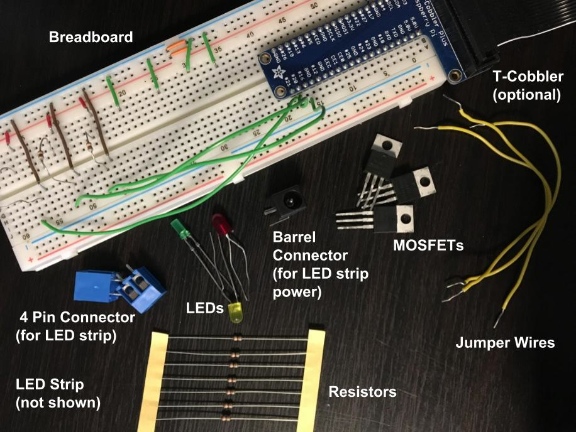
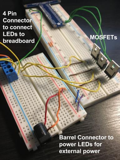
The T-Cobbler connects to the 40 pin on the Raspberry Pi and connects and labels the 40 pins on the Breadboard. The 4 pin connectors (in my case, two of the two pin connectors) connect the breadboard to the LED wires. The Barrel Connector is for powering the LED strip (power cable on the LED strip connects to a barrel connector). Though we will be using a LED strip in the final project, it’s easier to start with some individual LEDs to test. Also, if you messed up, you would only ruin a 15 cent LED instead of an $18 LED strip.
Setup 1
For those of you who have never worked with a Raspberry Pi before, raspberrypi.org has a lot of great resources. I would highly recommend their physical computing-with python tutorial. Also, a basic understanding of python would be helpful.
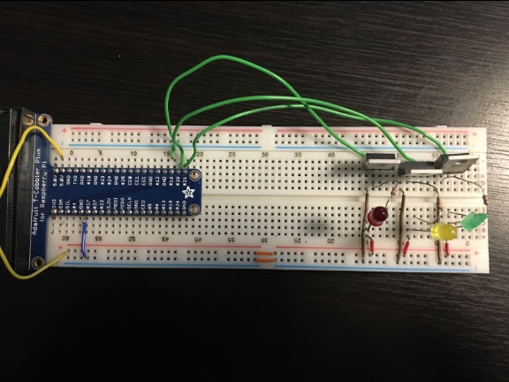
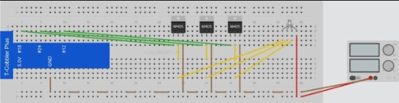
To get started, line up 3 different colored LEDs and connect each to a resistor. We are using 3 different LEDs because on the LED strip, each color is handled separately (with a 4th wire for power). After the LEDs and resistors are in, connect 3 MOSFETs to the Pi and each to its own LED + resistor pair.
For those of you who have never worked with MOSFETs before, a MOSFET is a transistor that allows you to reduce the current put out by the Pi. We are using it because we have an LED strand with 300 LEDs connected on the strand, which would draw a large amount of current, which could potentially fry the Pi.
The MOSFET will allow the Pi to only have to power the signal for the LEDs, while an external power source can power the actual LEDs. On the MOSFET, the gate connects to the Pi GPIO, drain connects to the LED and resistor, and source connects to ground. Depending on your MOSFET, the order of the gate, drain, source pins may change.
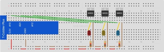
Each GPIO is connected to the Gate pin on the MOSFET (GREEN). The Drain pin on each MOSFET is connected to a LED (YELLOW), which is connected to a resistor, which is connected to power (RED). The Source pin on each MOSFET is connected to ground (BROWN).
The LEDs need to be placed such that the anode (the longer leg) points towards the power source and the cathode (the shorter leg) points toward the MOSFET.
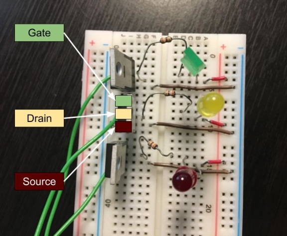
Note: I placed the MOSFETS facing away from the LEDs, so the pin order is (from top to bottom) Gate, Drain, Source.
Programming LED Library
First, it’s helpful to have a library to control your LEDs based on their pin number. I chose the pigpio library because it has smooth PWM transitions. Next, experiment with what you can do with the LEDs. Come up with your own library of patterns that you want your LED strip to be able to do. I personally wanted to be able to control the color through RGB values and play various patterns like fading between two colors or cycling through the colors of the rainbow.
Setup 2
Once you have your python library of patterns, replace your individual LEDs with the LED strip. You will also have to power the LEDs with the power source the LED strip came with, otherwise you will not have enough power to light up the LEDs.
Each GPIO is connected to the Gate pin on the MOSFET (GREEN). The Drain pin on each MOSFET is connected to its corresponding color on the LED strip (YELLOW). The 4th pin on LED strip connects to power (RED). The Source pin on each MOSFET is connected to ground (BROWN).
Programming External Control
Next, we need to be able to control this Raspberry Pi externally. The quickest, easiest, and most straightforward way to control the Pi remotely is by creating a website. This will definitely not be the most secure or cohesive way to do it, but it is the fastest. We need three different pages, an HTML site for us to input our LED commands, a PHP page to save information to the database, and a page that simply prints out data for our Pi.
Server Side
On the HTML page, you need the user to input commands like on or off, what color the lights should be, or what pattern you want to run. When the user clicked the submit button, the page would save the data in the database.
The second page just needs to export the information currently in the database in JSON.
Client Side
Back on the Pi, you need a script that continuously pulls the JSON data from the web server, parses it, and sends the proper commands to the LED Strip. Again, this is not a secure or efficient solution, but it is a really quick way to get something working.
Final Project Phase
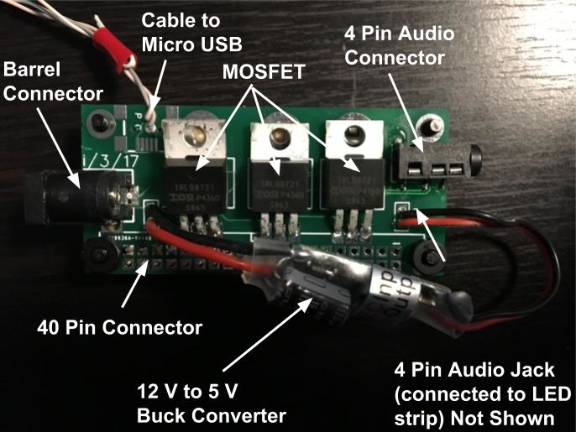
Once the project is functional, it’s time to condense the project into one compact solution. First, you need to condense the sprawling breadboard configuration. I knew I wanted my final solution to be small, so I converted my setup to a PCB board the size of a Raspberry Pi Zero.
I also didn’t want to have both my Pi and my LED strip running off two different power sources, but the LED strip runs off 12V while the Pi runs off 5V. So we grabbed a 12V to 5V buck converter to my PCB setup. I also added a power and ground hole on my PCB to send power to the Pi through a micro USB cable.
I then still needed the LED power jack, 3 MOSFETs, 40 pin connector for Pi (so that the board can sit right on top of the Raspberry Pi Zero), a 4 pin connector for the LED strip (I used a 4 pin audio jack in my PCB), a wifi dongle, and a micro USB to USB cable to be able to connect the wifi dongle to the Raspberry Pi Zero.
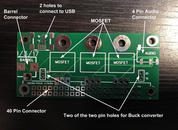
I used EasyEDA to design and print my PCB. I had to solder the pieces separately, but I was able to get the PCB up and running quickly.
You need to move the Pi image or SD card you used in the practice phase of the project from the Raspberry Pi 3 to the Raspberry Pi Zero. You also need to have your JSON search script run on boot.
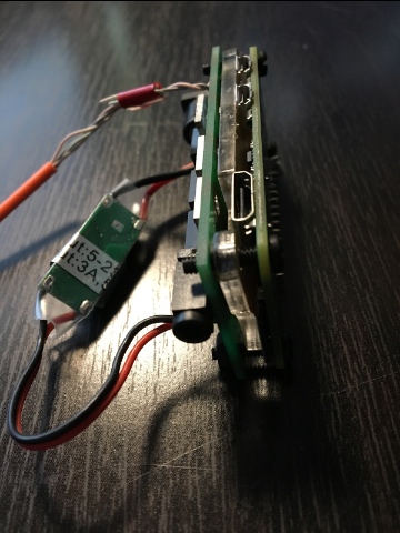
Also, I designed my board such that my PCB rests right on top of the Raspberry Pi Zero. This requires some sort of non-conductive layer in between the two boards. I just used a Raspberry Pi Zero case, but you can also use electrical tape or hot glue.
Feel free to stick your contraption in a case of some sort. An Altoid tin would easily fit, but you would have to line the inside with a non-conductive material and cut holes for the power cord and for the power switch. You could always customize your own case with a 3D printer too.
How to Control LED Lights with a Raspberry Pi: Future Additions
There are plenty of other ways to control your LED strip! We had another intern work with Slack’s interface and add commands on our internal slack channel to control the LED strip. You could also experiment with connecting your phone via bluetooth or create your own creative controller.
We’d love to hear how you improve on this — make sure that you let us know how your own project went!